
A hydrostatic test permits concealment only when the tested pipework and approval record match
“The gauge held” is not permission to close a ceiling. Release pipework only when the recorded test boundary, service, material, design and test pressures, hold period, calibrated instruments, inspection result and signatures all match the installation. The record should also identify the project location, governing authority or utility, approved specification, method statement and inspection-request status.
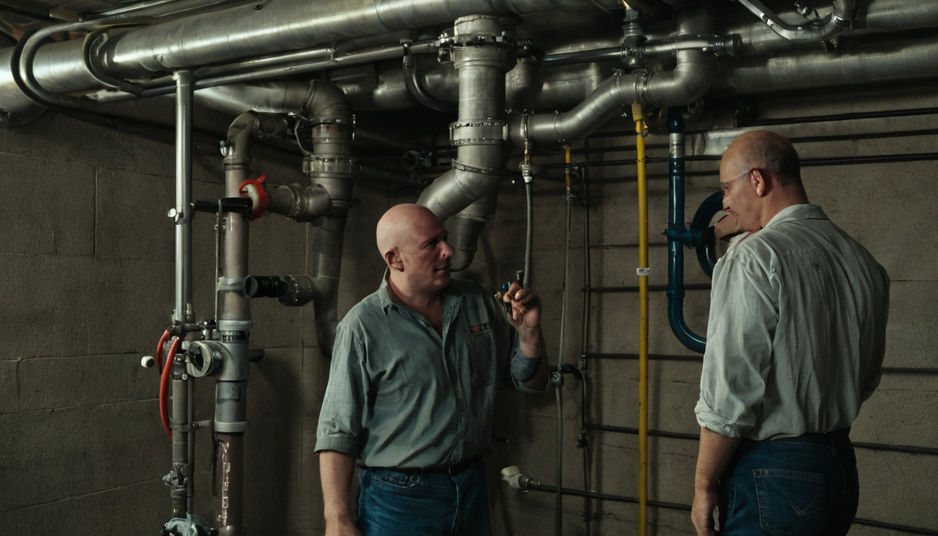
A hydrostatic test permits concealment only when the tested pipework and approval record match shown as an editorial planning reference.
What does a hydrostatic test confirm before UAE pipework is concealed?
Confirm that the tested assembly met the specified pressure-based acceptance criteria at the recorded time. The inspection may also need to establish that no visible leakage, joint movement or distortion occurred. The result does not prove lifetime reliability or cover isolated equipment, omitted branches, temporary closures, later alterations or workmanship outside the marked boundary.
What does a signed hydrostatic test certificate actually signify?
Read each signature according to the project quality plan. Contractor, consultant, client and authority signatures can represent different checks rather than blanket approval. Concealment release should include the marked drawing, calibration records, photographs, closed punch items and accepted inspection request. The next decision is which system-specific pressure and hold period govern the test.
Hydrostatic test pressure and hold time must be selected by system, standard, and manufacturer
No universal pressure or hold period applies to every UAE pipe installation. Confirm the service, adopted standard, authority conditions, component ratings and manufacturer procedure before approving a pressure testing method.
Which requirement governs when an authority rule, project specification, standard, and manufacturer instruction differ?
Check the contract document-precedence clause and obtain written designer or consultant clarification for every conflict. Do not simply choose the highest pressure. The test must satisfy applicable authority or utility conditions without exceeding the rating of any pipe, fitting, valve, flexible connector, equipment connection, temporary closure, hose or manifold within the boundary.
For work in Dubai, verify the applicable edition, permit conditions and project approvals alongside the Dubai Building Code published by Dubai Municipality. Manufacturer limits remain important even where a project specification adopts an international standard.
BS EN 806-4, BS EN 805, and ASME B31.9 apply to different pipework scopes
Map each service to its contract-adopted document before entering pressure or duration values in the method statement.
| System | Candidate governing document | Method or medium | Pressure and duration source | Acceptance evidence | Required clarification |
|---|---|---|---|---|---|
| Internal potable water | BS EN 806-4, if adopted | Approved clean water | Specification and manufacturer procedure | Readings, visual inspection and marked boundary | Material-specific stabilization and test cycle |
| Chilled water | ASME B31.9 or project specification, if adopted | Approved water | Design basis, specification and component limits | Stable result and inspected joints | Equipment exclusions and elevation effects |
| Fire sprinklers | NFPA 13 and fire approval conditions, if adopted | Specified test medium | Approved fire specification | Witnessed fire-system test record | Civil defence witness and acceptance requirements |
| Fire standpipes | NFPA 14 and fire approval conditions, if adopted | Specified test medium | Approved fire specification | Signed readings and inspection record | Required fire-system witnesses |
| External water networks | BS EN 805 or utility specification, if adopted | Approved water | Hydraulic profile and utility criteria | Network test sheet and permitted-loss assessment | Utility procedure and section boundaries |
| Gravity drainage | BS EN 12056 and drainage specification, if adopted | Water or air as specified | Specified head, procedure and duration | Drainage inspection record | Different methods for drains, stacks and flow tests |
For vertical pipework, check pressure at the lowest and highest elevations. The lower point must stay within every component rating while the upper point reaches the required test condition.
Drainage testing should not be labelled hydrostatic pressure testing without checking the specified method
Separate gravity drainage tests from pressurised service-pipe tests. The approved drainage specification should define the water head or air procedure, section limits, duration and acceptance criteria. Once those values are fixed, the next release question is whether the gauge can measure them credibly.
A pressure gauge is acceptable only when its range, resolution, calibration, and location suit the test
The pressure gauge must display the intended hydrostatic test pressure clearly without overload or operation in an unreadable part of its scale. The approved method should define the required range, accuracy, resolution, calibration status, instrument identity, connection point and elevation.
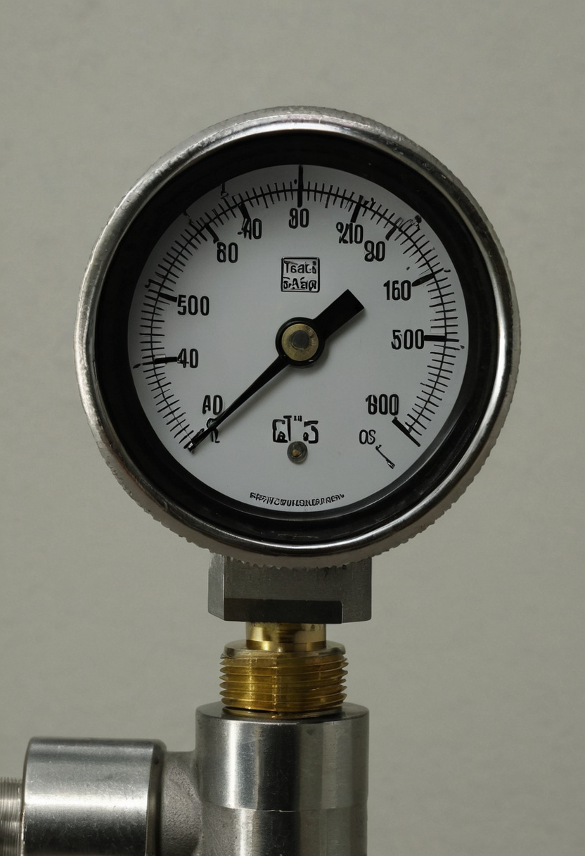
A pressure gauge is acceptable only when its range, resolution, calibration, and location suit the test shown with practical context cues.
How should the gauge range be chosen for a hydrostatic test?
Select the gauge from the intended test pressure, not the normal operating pressure. Compare the test pressure with available gauge ranges and instrument data. The scale must show relevant changes clearly while keeping the test pressure within the gauge rating. Confirm the specified accuracy class, dial size and minimum resolution instead of assuming universal values.
Check the entire pressure assembly before filling. The pump, hoses, manifold, isolation valves, temporary connections and relief arrangement must suit the intended conditions. Record each second gauge, digital recorder or temperature logger where the approved procedure requires one.
Position the gauge at the approved connection point where it can be read safely. For a tall riser, record its elevation and apply any correction required by the designer or method statement because pressure varies with water-column height.
What must a UAE project verify on the calibration certificate?
Match the gauge identification or serial number to the certificate and test record. Verify the calibrated range, test points, measured errors, stated uncertainty, issue date, due date and laboratory details. Confirm ISO/IEC 17025 accreditation where the project requires it. A sticker alone does not establish traceability.
Reject an overdue, damaged, unreadable or out-of-tolerance gauge. Accepted instruments still need a controlled test sequence.
The hydrostatic test sequence must control air, temperature, temporary closures, and stored energy
Follow an approved boundary: fill slowly from a low point, vent high points, stabilize, pressurise in controlled stages, inspect, depressurise safely and drain through an approved route.
- Mark fill, vent and drain points, valve positions, temporary caps, blinds and excluded equipment on the test drawing, making the boundary unmistakable.
- Confirm the method statement and risk assessment define the pressurisation rate, exclusion zone, communications, responsible personnel and emergency depressurisation arrangement.
- Verify every hose, manifold, valve, plug and temporary closure is rated for the intended conditions and secured against movement.
- Record water and ambient temperatures, stabilization time, water source and approved discharge route.
Entrapped air makes hydrostatic pressure testing less safe and harder to interpret
Vent every identified high point while filling until water flows without visible air. Confirm that raised branches contain no isolated pockets. Compressed air stores energy and can make a failed cap, hose or plug more hazardous, so keep personnel away from temporary closures during pressurisation and depressurisation.
Thermoplastic pipework needs stabilization and manufacturer-specific test cycles
Apply the installed pipe and fitting manufacturer’s current procedure so expansion, creep and temperature effects are interpreted correctly. PPR, PEX, PVC and CPVC should not inherit a copper or steel sequence merely because the design pressure is similar.
Check the material class, dimensions, jointing method, minimum curing or cooling time, stabilization period, staged cycle and permitted pressure behaviour. These material-specific checks for copper, PPR, and PEX plumbing should match the approved submittal and method statement.
Hydrostatic test acceptance requires a stable result, a complete visual inspection, and closed defects
Passing is not established by one gauge photograph. The accessible boundary must meet the specified pressure behaviour while joints, valves, fittings, branches, supports, anchors, sleeves, penetrations and temporary closures are inspected for leakage, movement or distortion.
A pressure drop should be investigated before it is accepted or blamed on temperature
Investigate visible leakage first, followed by hoses and caps, isolation valves, trapped air, pump disconnection, gauge condition and material expansion. Record starting and finishing pressures, water and ambient temperatures, timestamps and required intermediate readings.
Accept temperature compensation or material-related behaviour only where the project criterion and manufacturer procedure permit it. Unsupported explanations do not release concealment. Active leaks, damaged supports, incomplete inspections and unexplained pressure loss remain hold-point items.
Repairs and modifications invalidate the affected hydrostatic test boundary until retesting is complete
Retest after repairing a joint, replacing a valve, adding a branch, changing a temporary closure or removing damaged pipe. Define partial or full retesting through the specification and corrective-action procedure, then issue revised boundary, repair, inspection and test records.
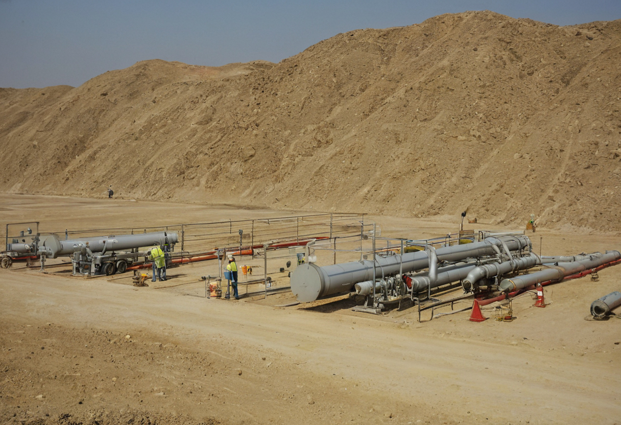
Hydrostatic test acceptance requires a stable result, a complete visual inspection, and closed defects shown with practical context cues.
A complete hydrostatic test pack is the evidence needed to release ceilings, shafts, and wall chases
The release pack must connect the tested pipework to controlled records. Keep concealment on hold wherever the boundary, exclusions, witness status or outstanding defects remain unclear.
What should a hydrostatic test certificate contain?
Record the project, system, level or zone, drawing reference, boundary, pipe material, size range and joint type. Add design and test pressures, stabilization and hold periods, test medium, relevant temperatures, timestamped readings, instrument identification, gauge range, calibration reference and validity.
State leakage, repairs, retest references and final disposition. Names, roles, signatures, dates and witness comments should follow the inspection and test plan. Document numbers and revisions should connect the material approval, method statement, inspection request, test certificate and concealment request.
A worked concealment-release check should expose gaps before approval
Audit the pack item by item. Photographs without readable instrument identity, pressure, time, location and representative joints are incomplete. An unsigned certificate, unexplained exclusion or drawing that does not match the installed route requires corrective action before release.
A short pre-concealment checklist gives the site team a final release gate
- Match the tested boundary to the latest coordinated drawing.
- Confirm all required contractor, consultant, client, authority or utility signatures.
- Close leakage, support, sleeve, firestopping, insulation and access punch items.
- Verify that no joint or branch was added after testing.
- Approve the concealment request and retain location photographs for handover.
Close access only after the location-marked, witnessed and defect-free boundary is fully traceable.
Hydrostatic test hold-point FAQ
What is a hydrostatic test for newly installed pipework?
A hydrostatic test fills an identified pipework boundary with an approved liquid and subjects it to specified test conditions. It supports acceptance only when the pressure result, visual inspection and records meet the applicable project requirements.
What does hydrostatic pressure testing confirm, and what does it not prove?
Pressure testing confirms the recorded boundary met stated criteria at the time of inspection. It does not prove lifetime reliability, correct water quality, cleanliness, commissioning performance or the condition of untested sections.
How are the correct test pressure and hold period selected for UAE pipework?
Select them from the approved project specification, applicable authority or utility conditions, contract-adopted standard, design information and manufacturer procedure. Resolve conflicts in writing rather than choosing the highest value.
What does a signed hydrostatic test certificate signify before concealment?
The certificate records the result and named witnesses for a defined boundary. Concealment still requires the accepted inspection request, closed defects, supporting records and any separate release required by the quality plan.
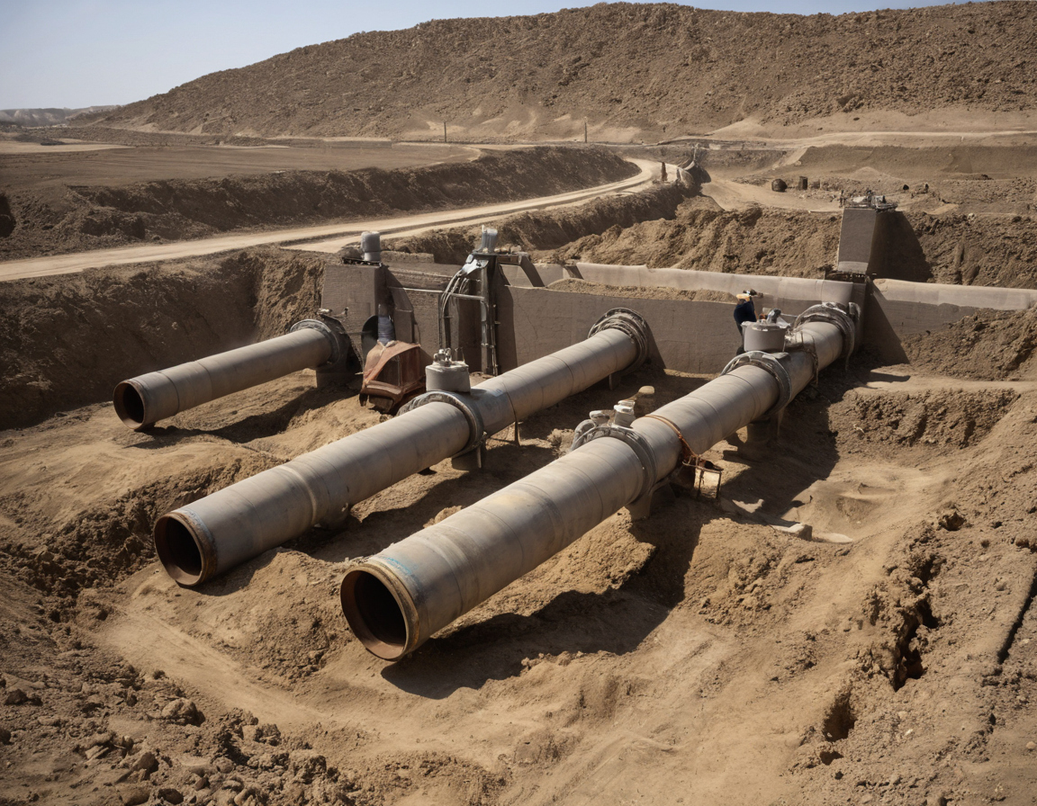
Hydrostatic test hold-point FAQ shown with practical context cues.
What affects the cost of a hydrostatic test on a UAE construction project?
Cost depends on boundary size, access, filling and drainage arrangements, calibrated instruments, witness attendance, temporary closures, water handling, repeat visits and retesting after defects or alterations. Clear test zoning and early witness planning reduce avoidable repetition.